
Connectors
Connectors are smart lines that link shapes together. Unlike regular lines, connectors stay attached to their shapes — move a shape and the connector follows.
Creating Connectors
- Press
Cor click the connector icon in the toolbar - Hover over a shape — you'll see connection points appear as small circles on the edges
- Click a connection point to start the connector
- Click a connection point on another shape to finish
The connector automatically routes itself between the two shapes.
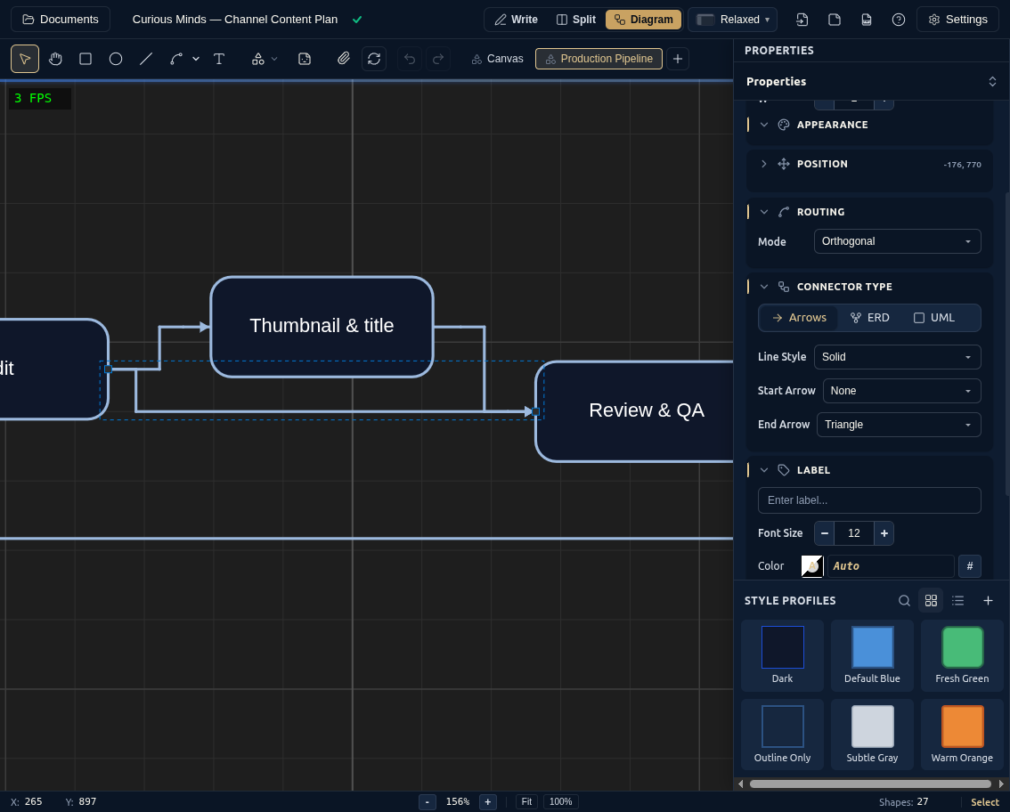
Connection Points
Every shape has connection points where connectors can attach — top, right, bottom, left, and center. They become visible when you hover over a shape with the Connector tool active. (The four corners are resize handles, not connection points.) Some library shapes — UML classes, ERD entities — also expose extra anchors on their individual rows or compartments.
Picking a Routing Style
Configure how a connector's path looks in the Property Panel:
- Orthogonal (the default) draws clean right-angle paths that route around shapes, and automatically adjusts when you move things — the safest choice for most diagrams, especially flowcharts and architecture diagrams.
- Straight draws a direct line from start to end. Good for simple diagrams or when you want the shortest visual path.
- Curved draws a smooth curve instead of hard angles — often reads better for organic or less rigidly structured relationships.
If a connector's path looks awkward after moving shapes around, switching routing style is usually the fastest fix.
Labels and Annotations
Click a connector's label area (or use the Property Panel) to add text. Labels float alongside the connector path and move with it — set where along the path it sits with the label position property.
UML sequence diagrams use connectors more specifically — synchronous/asynchronous markers, guard conditions, message numbering, and self-messages — covered in DocuShark's Software Engineering guides.
Arrowheads & Endpoints
A connector's ends are configurable in the Property Panel — add or remove an arrowhead at either end and choose its style. That's what turns a plain line into notation: one arrow reads as a flow, arrows at both ends as a two-way relationship, and no arrows as a simple association. For the complete list of endpoint and arrowhead options, see the Shape Properties reference.
Set a Default Connector Style
If you mostly draw one kind of connector, make it the default so every new connector starts that way. Go to Settings → General → Default Connector Type and choose Orthogonal or Straight. You can still change any individual connector's routing in the Property Panel afterward.
Tips
- Move connected shapes freely — connectors update their routes automatically
- Switch routing style if a connector's path looks awkward — sometimes straight or curved works better
- Connectors snap to the nearest connection point as you draw them
For the full list of connector properties (arrowheads, corner radius, activity-diagram flow types, and more), see the Shape Properties reference.